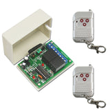
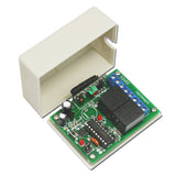
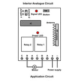
By using this motor remote control kit, you can remote control DC motor. Working modes include toggle, momentary and latching. Easy to wire and operate.The motor remote control kit is suitable for the motors of rolling blinds / doors, projection screens, awnings, pumps, winches, conveyors or other appliances and machines. Remote control distance is up to 1000M
Here is a video about how to use this wireless switch to open or close a valve.
https://www.youtube.com/watch?v=Njnr08DT0fY
Here is a video about how to use this wireless switch to remotely control a DC motor.
https://www.youtube.com/watch?v=mvWHDVpIi4g
Package Include:
1 x Receiver: S1FU-DC06 / S1FU-DC09 / S1FU-DC12 / S1FU-DC24
2 x Transmitter: C-3-2
1 x User manual
Feature:
Wireless control, easy to install
Control motors of rolling blinds / doors, projection screens, awnings, pumps, winches, conveyors or other appliances and mechanicals with DC voltage.
You can turn on/off the receiver with transmitter (remote control) from any place within a reliable distance; the wireless signal can pass through walls, floors and doors.
With characteristics of reverse power protection and over current protection
Audible / visual indication
Use microcontroller model of EM78P156, an 8-bit microprocessor designed and developed with low-power and high-speed CMOS technology.
Reliable control: The transmitter (Encoding) and the receiver (Decoding) use an 8-bit code.
One/several transmitters can control one/several receivers simultaneously.
If you use two or more receivers in the same place, you can set them with different codes.
Transmitting Frequency: 433MHz
Receiver:
Model No: S1FU-DC06 / S1FU-DC09 / S1FU-DC12 / S1FU-DC24
Control Modes: Inversion (Self-locking, Momentary, Interlocking)
Coding Type: Fixed code
Coding Setting: By learning
Power Supply (Operating Voltage): DC6V (S1FU-DC06), DC9V±1V (S1FU-DC09), DC12V±1V (S1FU-DC12), DC24V±1V (S1FU-DC24)
Output: DC6V (S1FU-DC06), DC9V (S1FU-DC09), DC12V (S1FU-DC12), DC24V (S1FU-DC24)
PCB size: 67mm x 50mm x 18mm
Case size: 75mm x 54mm x 27mm
Static Current: ≤6mA
Maximum Working Current: 10A
Transmitter:
Model No.: C-3-2
Channel: 3 CH
Remote Control Distance: 100m / 300ft (theoretically)
Encode: Fixed code by bonding pad encoded
Unit size: 58mm x 39mm x 16mm
Power Supply: 1 x 23A -12V battery (included, can be used for 12 months)
Usage:
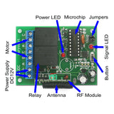
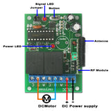
Connect the motor to Terminal B of relay 1 and relay 2.
Setting different control modes (We have set the receiver as Self-locking control mode before delivery. If you want to use other control modes, do as following operation):
Setting control mode Self-locking: Only connect Jumper-2.
Control mode Self-locking: Press -> Rotate; Press again -> Stop.
Press button ▲: Terminal B of relay 1 and relay 2 output + DC (1: +, 2: -), motor rotates in the positive direction.
Press button ▲ again: Terminal B of relay 1 and relay 2 no output, motor stops
Press button ▼: Terminal B of relay 1 and relay 2 output - DC (1: -, 2: +), motor rotates in the reversal direction.
Press button ▼ again: Terminal B of relay 1 and relay 2 no output, motor stops
Setting control mode Momentary: Only connect Jumper-1.
Control mode Momentary: Press and hold -> Rotate; Release -> Stop.
Press and hold button ▲: Terminal B of relay 1 and relay 2 output + DC (1: +, 2: -), motor rotates in the positive direction.
Release button ▲: Terminal B of relay 1 and relay 2 no output, motor stops
Press and hold button ▼: Terminal B of relay 1 and relay 2 output - DC (1: -, 2: +), motor rotates in the reversal direction.
Release button ▼: Terminal B of relay 1 and relay 2 no output, motor stops
Setting control mode Interlocking: Do not connect Jumper-1 and Jumper-2.
Control mode Interlocking: Press button ▲ and ▼ -> Rotate; Press button ■ -> Stop.
Press button ▲: Terminal B of relay 1 and relay 2 output + DC (1: +, 2: -), motor rotates in the positive direction.
Press button ▼: Terminal B of relay 1 and relay 2 output - DC (1: -, 2: +), motor rotates in the reversal direction.
Press button ■: Terminal B of relay 1 and relay 2 no output, motor stops


